
I need your help. By my calculations, counter-flow plate-type enthalpy exchangers don’t work. So either there is something wrong with my calcs, or there is an industry out there that should take a good look at themselves. Rotary-wheel enthalpy exchangers probably work, though I’ve heard grumbling about maintenance and repair from mechanical engineers who had them installed. A plate-type heat exchanger takes two air streams, one passing out of a building and the other passing in, and uses the temperature of the outgoing airstream to pre-condition the incoming air stream. An enthalpy exchanger is a heat exchanger which is also capable of using the wetness or dryness of the outgoing air to precondition the incoming air for humidity. A plate-type exchanger has no moving parts except for fans. Counter-flow exchangers have the optimum flow directions for exchanging heat and humidity. Early enthalpy exchangers used cellulose membranes—paper actually—to separate the airstreams and allow for moisture exchange. Current units typically have polymer cores, notable for their diamond- or lozenge-shape. Enthalpy exchangers are also called energy exchange ventilators, which helps describe their principal use in providing pre-conditioned fresh air.

I took an interest in this by imagining what a frame would look like that might hold a very thin membrane in counter-flow tension. Cores seemed awfully thick, where a thin membrane must, I figured, work better. My friend from Tyvek supported my interest—Tyvek seemed like a membrane candidate because it was vapor-permeable, and is found with a variety of properties. I mentioned this idea many years ago to my colleague John Straube, who dismissed it saying not enough permeance, permeance being the rate of moisture transport across the membrane. That didn’t stop me. I went on and developed what I modestly consider a brilliant origami solution to the problem of having a frame to hold membrane in counter-flow tension. The only thing standing between me and a lavish fortune for having the cheapest best enthalpy exchange core on the market was selecting and sizing a membrane.
The rest of this analysis hinges on a strong familiarity with psychrometrics and the physics of managing air flows. My apologies to readers who don’t have these preliminaries. You could simply trust my conclusions, but that misses the whole point. I am honestly puzzled why my calculations say that these devices don’t work, yet we have commerce in them at a fairly robust scale.
This analysis will make use of inch-pound, not metric, units. I happen to prefer metric, but the US is dogged in its adherence to these units. See the figure below.

The vapor barrier was invented in the US, and the notion of water vapor permeance for buildings took root in the US. This project is all about permeance—shorthand here for water vapor permeance. USians have a “feel” for membranes having a permeance of greater than, or less than, one perm. One perm is—you’ll love this—one grain per hour per square foot per inch of Mercury water vapor pressure difference. The unit of one grain has no use whatsoever on earth, seems to me, other than fitting into the US permeance definition. A pound equals 7000 grains. They needed a tiny weight measurement. (Recall a pound is a unit of weight not of mass, there is no current unit of mass in the inch-pound system. This analysis uses “pound” as if it were mass that needs to be conserved. And how do you abbreviate a grain without confusing it with a gram? Welcome to my world.) Permeance conversions into metric use nanograms for the mass unit. This might start giving you a hint of the upcoming problem—we are going to be exchanging pounds or kilograms per hour with our membranes, and their transfer coefficient is rated in grains or nanograms. Smells like trouble. I looked for permeance values on websites selling enthalpy cores and couldn’t find any. Perhaps I did not look hard enough.
I use spreadsheets. I’ve consigned psychrometric calculations to function macros—for vapor pressure, humidity ratio, and specific volume (the reciprocal of density). The question I seek to answer is: for a given membrane permeance and equipment efficiency, how much membrane surface area do I need to achieve the moisture transfer?
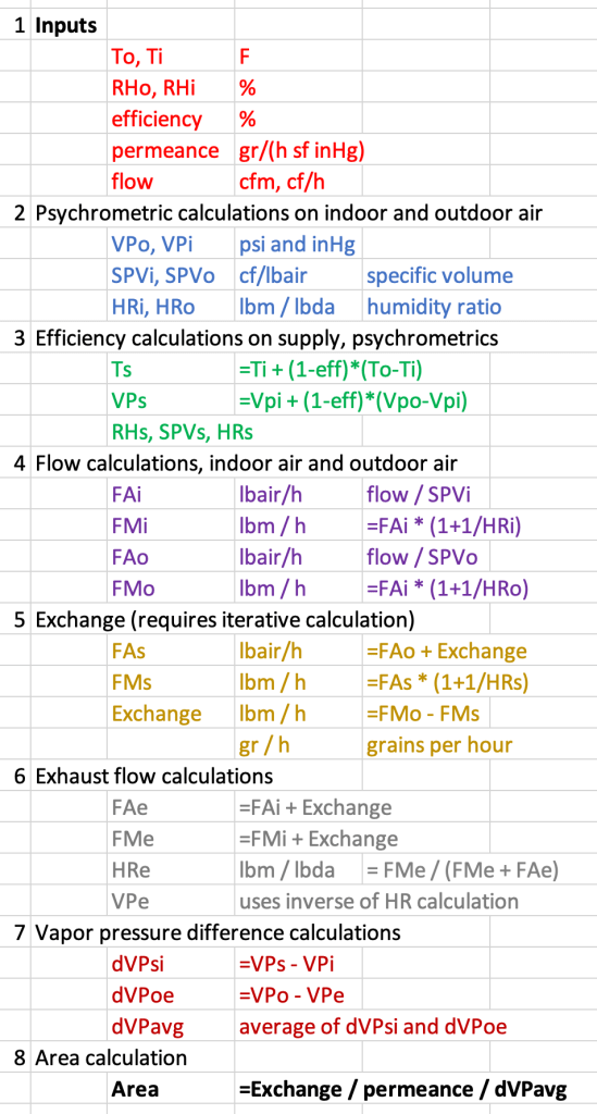
- Select inputs:
- indoor temperature and relative humidity, outdoor T and RH. These calculations work for outdoor air warmer than indoor, and also cooler than indoor. The hot-humid outdoor condition is shown.
- Air flow rate—I selected having the same volume flow rate in both streams, and 100 cfm is a good starting point.
- Efficiency of the equipment—I used a single value for both temperature efficiency and vapor transfer efficiency, and 70% is a good guess. Spreadsheet can be easily modified for two different efficiencies.
- Permeance—it’s hard to find membranes with higher than 15 perms, but I use values here in the 25 range.
- Calculate vapor pressure, specific volume and humidity ratio at indoors and outdoors, using standard psychrometric relations.
- Use efficiency input to determine what the supply temperature and vapor pressure need to be, and do the supply psychrometric calculations.
- Calculate the mass flow of air and of water in the outdoor-to-supply air stream, from the volume flow rate.
- Calculate what the moisture exchange rate across the membrane needs to be, using outdoor air flow calculations.
- Calculate conditions at the exhaust.
- Calculate vapor pressure difference across the membrane at both ends of the exchanger, and the average vapor pressure difference.
- Use permeance, vapor pressure difference and moisture exchange across the membrane to calculate the needed area, using Exchange = Perms x area x pressure difference.
These steps are shown in the figure below. And also, a layout of the spreadsheet I used.
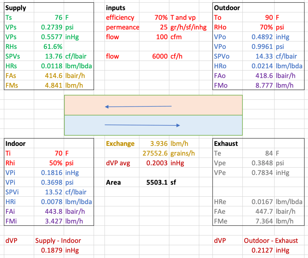
Answer: For an efficiency of 70%, a permeance of 25 perms and airflow 100 cfm in each stream, the required surface area is over 5500 square feet of membrane. Too much membrane. A spreadsheet permits the user to vary the input values. What we see is that modifications to the permeance or the airflow has a direct, linear impact on the needed area. Curiously enough, the surface area needed is quite independent of the indoor and outdoor conditions selected. This begins to make sense when we consider that creating more extreme conditions leads to a greater rate of transfer exchange across the membrane.
What’s the takeaway? Well, for one, when John Straube speaks, you listen. For another, a guy like me who loves running numbers can find himself in a bit of a pickle, and needs to turn to a world full of utterly unknown strangers like you, asking what the hell is going on here. That can only be done with humility, such that when one of you strangers coughs politely and points out where I’m wrong and the industry is right, I am obliged to say thanks and you’re right and I really appreciate the input and if I’d contacted you first I’d have saved myself much embarrassment. Which I’m fully prepared to do. Know why? Because now I proceed with my brilliant origami frame and begin swimming in my newfound lavish riches.
Update 27 January
I have constructed a spreadsheet using metric units. The results are similar to those in inch-pound units. If the comments show interest, I can publish it as well. I made a psychrometric error in the above calcuation: specific volume is the ratio of mass to dry air volume, not the ratio of mass to air volume (as shown in the example above). The error is on the order of 1%, and suggests need for greater surface area, not less.
I spoke with an engineer for a major firm fabricating and marketing plate-type enthalpy exchangers. He noted that their materials may have a permeance of 20 micrograms per second per meter squared per Pascal of vapor pressure difference. This translates to 236 perms. If that is 10x the estimate used in the example above, then the required surface area is 1/10 of the result shown in the example.

Leave a comment