
William Thompson, Lord Kelvin, made a claim in 1869 that vapor pressure is reduced over a curved meniscus compared to vapor pressure over a flat surface. He bases this on Laplace’s finding of 65 years earlier that the liquid pressure in a liquid is raised or lowered depending on whether the liquid meniscus (measured from in the liquid) is convex or concave. A raindrop is very slightly at higher pressure than water at that elevation, and the water raised in a capillary tube is at a slightly lower pressure than water at the flat surface. Pressure in the water is what forces the exchange of molecules across the interface, from liquid to vapor and back again. Thus water at lower liquid pressure sponsors a lower equilibrium vapor pressure. The liquid pressure variation with raindrop or curved meniscus is minuscule, so the vapor pressure variation would be minuscule as well.
Perhaps. I plan to measure the equilibrium vapor pressure where the water source is capillary water. I’ll use an airtight jar with a temp/RH sensor inside. I’ll use a bundle of capillary tubes sitting in a water pool. I’ll use a few drops of mineral oil on the pool surface to prevent evaporation from the bulk of the water, leaving only capillary water in communication with the air in the jar. We’ll see. Somehow I suspect the equilibrium RH of the jar to be lower than the estimate we get from Thompson.
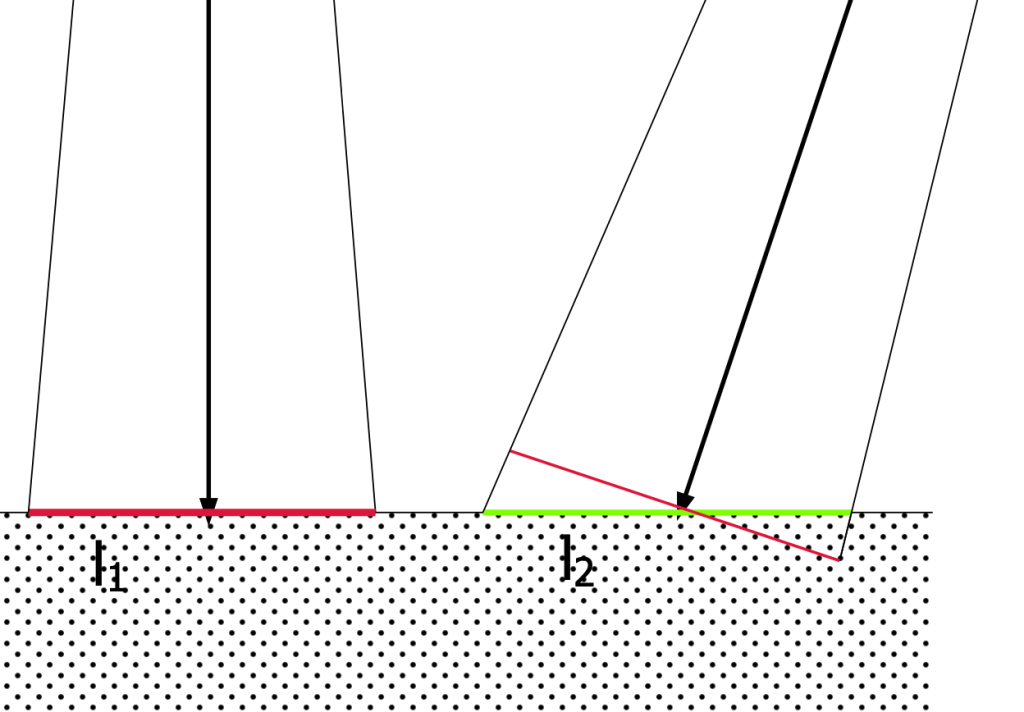
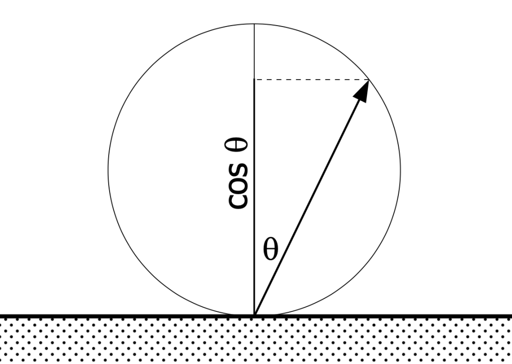
To explain why, we need to go to optics described in Johan Heinrich Lambert’s 1760 Photometria. He sought to explain why the apparent luminance of a diffuse-light (non-reflecting, non-directional) surface remains the same whether the surface is viewed directly—normal to the plane of the surface—or at an angle. See figures 1 and 2. Assume we have an observation cone of the same shape and size. It will “see” a circle of the surface (l1, red) when viewed normal, and, if viewed from an angle, will “see” an ellipse (l2, green), larger in area than the circle. The area of the ellipse will equal the area of the circle, divided by the cosine of the angle. So the luminous intensity of the circle must be greater than the intensity viewed from an angle. This is Lambert’s Law, where the intensity of light emittance from the surface is a function of the angle of emittance, and the intensity at an angle equals the intensity normal times the cosine of the angle. See figure 3. The intensity effect and the area effect cancel each other out, so the luminance doesn’t change with observation angle.

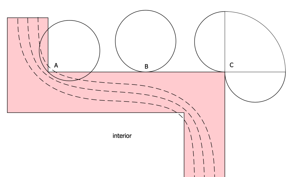
This helps explain something we see in infrared thermography. If a building is warm inside compared to the outdoors, then outside corners of the building appear especially cold, and any inside corners appear especially warm. See figure 4. The diagram at figure 5 explains the two effects at work here. The principal effect has to do with simple heat conductance as represented by isotherms (dashed lines) in any two- or three-dimensional arrangement with corners. A secondary effect is seen in emissive intensity. The circle at B represents intensity typical of radiant effects on a flat surface, as seen in Figure 3. At an outside corner there is more exchange with the outdoor environment (C), and at an inside corner there is less.

Let’s turn our arrows around. A water body is composed of water molecules at high speed doing 3-dimensional colliding with one another and with the bounding surfaces. We could imagine that the molecules are all traveling at the same speed, the mean speed which is determined by temperature. And suppose that we have a single hole in the surface that allows the escape of any molecules that have the good fortune to make it through the hole. See Figure 6. If we imagine all of the molecules that are aimed in the general direction of the hole, what is their probability of making it through? Just as, with optics, a similar cone leads to a larger apparent area, in this case, a similar actual area leads to a smaller cone. And smaller by the cosine of the angle. See Figure 7.

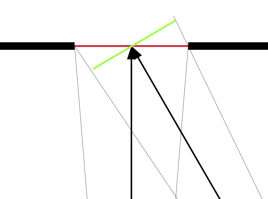
Which leads us to estimating what is the vapor pressure reduction over a curved meniscus, Figure 8. If we look at a “hole” at point P, and a circle which represents the Lambert probability of a molecule making it through the hole, we note that some of the molecules, the ones at an angle close to the meniscus like the small blue arrow barely visible at the top of the circle, will be emitted not into the air but eventually back onto the water surface. In a sense, the air above the meniscus will not be affected by emission from the surface back onto the surface. The molecules going surface to surface represent those not going into the air, thus they represent the vapor pressure reduction due to curvature. The emission of light from a diffuse surface, and the emission of molecules from a meniscus, follow the same rules regarding emission direction compared to the plane of the surface.

What vapor pressure depression does this represent? The math makes my head hurt, as my colleague Anton used to say. For any point P, radius R and angles theta1 and theta2 , we can calculate the areas of the segments of surface-to-surface emission. We’d need to combine that with the probabilities, calculated using the Lambert cosines we’ve grown to love. And we’d need to integrate that over all the possible points P. It’s doable.
I’m much more interested in my physical experiment. I’ll tell you how these work out.

Leave a comment